
Choosing a CNC lathe spindle involves more than matching a spindle nose designation to a chuck size. The spindle nose, chuck interface, through-hole, drawtube, cylinder, workholding method and permissible operating speed must be evaluated as one complete system.
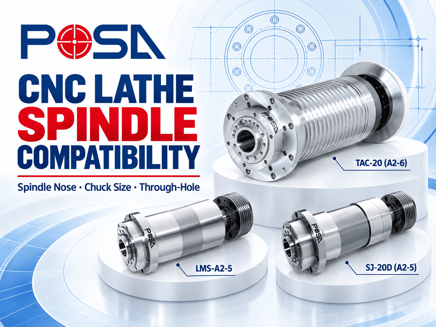
We provide built-in and belt-drive CNC lathe spindles for different machine configurations. In this guide, we explain how to review compatibility using our LMS built-in spindle models and TAC and SJ-20D belt-drive spindle models as practical examples.
1. What Must Be Matched in a CNC Lathe Spindle System?
A CNC lathe spindle does not operate as an isolated component. It connects the drive system, bearings, chuck or collet, clamping mechanism and workpiece. Compatibility therefore has to be evaluated from both the machine side and the workholding side.
We recommend starting with the workpiece and machining requirements before selecting a spindle model. Bar diameter, workpiece weight, required spindle speed, machining torque, clamping method and machine layout all influence the final specification.
The main compatibility points normally include:
- Spindle nose type and mounting dimensions
- Chuck or collet interface
- Nominal chuck size and permissible chuck mass
- Spindle through-hole and drawtube inner diameter
- Hydraulic cylinder requirements when a power chuck is used
- Spindle speed and the allowable speed of the workholding system
- Belt, motor or built-in drive configuration
- Lubrication, cooling, sealing and machine installation conditions
Key Takeaways
- Begin with the workpiece, machining process and workholding method.
- Review the spindle, chuck, actuator and machine structure as one system.
- Do not select a spindle using speed, power or through-hole data alone.
2. How Does the Spindle Nose Affect Chuck Installation?
The spindle nose defines the mechanical connection between the spindle and the workholding device. A designation such as A2-4, A2-5, A2-6 or A2-8 identifies a standardized interface size, but the designation alone does not complete the compatibility review.
The chuck or chuck adapter must match the spindle nose dimensions, mounting arrangement, locating surface and fastener pattern. Runout, concentricity and installation accuracy also affect machining quality and bearing load.
The A-type spindle nose dimensions commonly referenced in machine-tool design are covered by ISO 702-1. Final installation must still be verified against the spindle and workholding manufacturers' drawings and operating requirements.
Information to confirm before chuck installation
- Exact spindle nose designation and dimensions
- Chuck backplate or direct-mount interface
- Mounting bolt specification and tightening procedure
- Chuck mass, diameter and center-of-gravity position
- Permissible operating speed of the spindle and chuck
- Required runout and concentricity after assembly
Key Takeaways
- Matching the A2 designation is only the first compatibility check.
- Confirm mounting dimensions using the applicable technical drawings.
- Evaluate chuck mass and overhang before approving an adapter.
3. Does Chuck Size Alone Determine Compatibility?
No. A listed chuck size is a useful preliminary reference, but it does not confirm that every chuck of the same nominal diameter can be mounted directly on the spindle.
Two chucks with the same nominal size may have different mounting arrangements, body mass, maximum speed, jaw configuration and actuator requirements. A larger chuck may accommodate a larger workpiece or provide a wider jaw arrangement, but it does not automatically provide greater clamping force.
Clamping performance depends on factors such as chuck construction, hydraulic pressure, cylinder output, drawtube force, jaw type, jaw position, gripping diameter and spindle speed. Because centrifugal force reduces effective gripping force at higher speed, the complete chuck system must be checked for the intended operating range.
Key Takeaways
- Nominal chuck diameter does not confirm direct-mount compatibility.
- A larger chuck does not automatically produce higher clamping force.
- Use the lowest applicable speed rating for the complete assembly.
4. Is Spindle Through-Hole Diameter the Same as Bar Capacity?
The spindle through-hole is the internal opening specified for the spindle itself. Usable bar capacity is the maximum bar diameter that can pass through the complete machine and workholding system under actual operating conditions.
These values can differ because the material may also need to pass through a drawtube, collet, chuck bore, actuator, guide liner or bar feeder component. The smallest effective opening becomes the limiting diameter.
Bar-feeding path to verify
- Bar feeder outlet or guide channel
- Rear spindle connection
- Hydraulic cylinder bore, when applicable
- Drawtube inner diameter, when applicable
- Spindle through-hole
- Chuck, collet or workholding bore
- Guide liner and required operating clearance
The nominal bar diameter should not equal the smallest component bore without considering clearance, material straightness, bar variation, guide-liner design and rotational conditions. These factors are especially important in automatic bar-feeding applications.
Key Takeaways
- Spindle through-hole and usable bar capacity are not interchangeable specifications.
- The smallest effective passage controls the actual bar-feeding limit.
- Allow suitable clearance for bar variation and operating conditions.
5. Comparing POSA LMS, TAC and SJ-20D CNC Lathe Spindles
POSA MACHINERY CO., LTD. offers built-in and belt-drive spindle configurations for CNC lathe applications. The LMS models shown below are built-in spindles, while TAC and SJ-20D are belt-drive spindles.
The following table is intended for preliminary model comparison. A final selection must be based on the required speed, torque, bearing arrangement, chuck interface, actuator system and machine installation conditions.
| Model | Drive Type | Spindle Nose | Listed Chuck Size | Listed Through-Hole |
|---|---|---|---|---|
| LMS-S20 | Built-in spindle | Collet | 5 in | Ø21 mm |
| LMS-A2-4 | Built-in spindle | A2-4 | 5 in | Ø43 mm |
| LMS-A2-5 | Built-in spindle | A2-5 | 6 in | Ø56 mm |
| LMS-A2-6 | Built-in spindle | A2-6 | 8 in | Ø62 mm |
| TAC-10 | Belt-drive spindle | A2-4 | 5 in | Ø36 / Ø45 mm |
| SJ-20D | Belt-drive spindle | A2-5 | 6 in | Ø56 mm |
| TAC-20 | Belt-drive spindle | A2-6 | 8 in | Ø66 mm |
| TAC-22 / TAC-35 | Belt-drive spindle | A2-8 | 10 in | Ø80 / Ø86 mm |
| TAC-220 | Belt-drive spindle | A2-15 | 18 in | Ø100 mm |
Specifications are presented as preliminary selection references. Where alternative values are shown, confirm the applicable product configuration with POSA. Product specifications may be updated, and final compatibility must be verified using the latest approved drawings and project requirements.
Built-in spindle or belt-drive spindle?
A built-in spindle integrates the motor into the spindle assembly and can support a compact drive layout with direct power transmission. A belt-drive spindle transfers power from an external motor through a belt-and-pulley system and can provide greater flexibility in motor selection and transmission ratio.
Neither configuration is universally better. The appropriate choice depends on target speed, torque, thermal behavior, available machine space, service requirements and overall machine architecture.
Key Takeaways
- LMS models are built-in CNC lathe spindles.
- TAC and SJ-20D are belt-drive CNC lathe spindles.
- Use the table for initial comparison, not as final installation approval.
6. CNC Lathe Spindle Compatibility Checklist Before an RFQ
Providing complete application information allows us to review the spindle configuration more accurately and reduces the risk of mismatched interfaces during machine design.
- Machine type and intended machining process
- Workpiece material, size and maximum weight
- Required spindle speed range
- Required torque and duty cycle
- Chuck or collet brand, model and mounting interface
- Required nominal chuck size
- Spindle nose designation
- Required spindle through-hole
- Target bar diameter and required operating clearance
- Drawtube and hydraulic cylinder details, when applicable
- Motor data and drive configuration
- Lubrication, cooling and sealing requirements
- Machine installation space and interface drawings
- Runout, accuracy and inspection requirements
If the final chuck or actuator has not yet been selected, provide the workpiece range and intended clamping method. We can use this information as part of the spindle specification discussion, but the machine builder remains responsible for validating the complete machine, workholding and safety system.
Key Takeaways
- Include workpiece, workholding, performance and installation data in the RFQ.
- Provide drawings whenever mounting dimensions or clearances are critical.
- Final approval must cover the complete machine and workholding system.
7. FAQ About CNC Lathe Spindle Compatibility
Is the CNC lathe spindle through-hole the same as usable bar capacity?
No. The through-hole is a spindle specification. Usable bar capacity is limited by the smallest effective diameter in the complete bar-feeding path, including the drawtube, actuator, chuck or collet, guide liner and bar feeder.
Can any 6-inch chuck be installed on an A2-5 spindle?
Not automatically. The chuck mounting interface, backplate, fastener arrangement, chuck mass, maximum speed and actuator requirements must be verified using the applicable technical drawings.
Does a larger chuck always provide greater clamping force?
No. Clamping force depends on chuck design, actuator output, hydraulic pressure, drawtube force, jaw position, gripping diameter and spindle speed. Chuck diameter alone does not determine effective gripping force.
Can an adapter be used to install a larger chuck on a smaller spindle nose?
An adapter may be mechanically possible in some applications, but it must not be approved using dimensions alone. Chuck mass, overhang, rotational speed, centrifugal force, spindle-bearing load and machine structure require a complete engineering review.
What limits the maximum speed of the spindle and chuck assembly?
The assembly must not exceed the lowest applicable speed rating among the spindle, chuck, jaws, adapter and related components. Workpiece mass, jaw extension, imbalance and gripping conditions may require a lower operating speed.
What information should be provided when requesting a POSA CNC lathe spindle?
Provide the machine type, machining process, workpiece range, required speed and torque, spindle nose, chuck or collet information, target bar diameter, through-hole requirement, actuator details, motor data and machine interface drawings.