
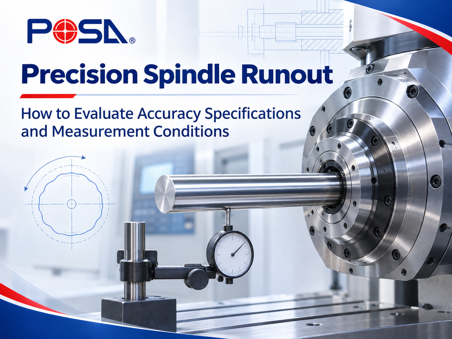
When comparing precision spindle specifications, a lower runout value does not necessarily indicate better overall accuracy. A spindle rated at 2 μm and another rated at 3 μm may have been measured at different locations, making a direct comparison misleading.
At POSA MACHINERY CO., LTD., we manufacture precision machine tool spindles for CNC lathes, machining centers, grinding machines, and other industrial applications. Our published product specifications include accuracy references at the spindle nose, taper, and test bar.
Understanding these differences helps machine tool manufacturers, engineers, and purchasing teams evaluate spindle specifications more accurately. This guide explains how spindle runout is measured, which conditions affect the results, and how to establish appropriate accuracy requirements.
Precision spindle runout values cannot be compared using numbers alone. Buyers must identify the measurement location, reference surface, test conditions, and applicable acceptance criteria before determining whether a spindle meets their machining requirements.
1. What Is Spindle Runout and Why Does It Matter for Precision Machining?
Spindle runout refers to the variation indicated when a specified spindle surface or mounted reference component rotates relative to a measurement instrument.
For precision machining, excessive runout can contribute to dimensional variation, uneven cutting engagement, and inconsistent surface quality.
Two common types of runout are:
- Radial Runout: Variation measured perpendicular to the spindle's rotational axis. It can affect tool positioning, concentricity, and cutting consistency.
- Axial Runout: Variation measured parallel to the spindle's rotational axis, usually at a rotating face. It can influence the positioning of components mounted against that face.
Runout values are commonly expressed in millimeters (mm) or micrometers (μm). For example, 0.005 mm equals 5 μm.
However, spindle runout is only one aspect of precision spindle performance. A single runout measurement does not fully describe rotational accuracy, rigidity, or behavior during machining.
- Spindle runout indicates variation at a specified measurement location.
- Radial and axial runout represent different measurement directions.
- Runout specifications must be interpreted together with their measurement conditions.
2. Where Should Spindle Runout Be Measured: Spindle Nose, Taper, or Test Bar?
The measurement location is one of the most important factors when comparing precision spindle specifications.
Spindle nose, taper, and test bar measurements evaluate different reference features. Even when their values use the same unit, they should not automatically be considered equivalent.
Comparison of Spindle Runout Measurement Locations
| Measurement Location | Measurement Purpose | Key Consideration |
|---|---|---|
| Spindle Nose | Evaluates runout at a specified spindle nose reference surface. | Measurement position and surface geometry. |
| Spindle Taper | Evaluates runout of the spindle's tapered interface. | Taper geometry and measurement reference. |
| Test Bar | Evaluates indicated variation on a mounted precision test bar. | Test bar accuracy, seating, and measurement distance. |
Spindle Nose Measurement
The spindle nose provides an important mounting reference for workholding equipment, particularly in CNC lathes.
Runout measured at the spindle nose helps evaluate the geometric accuracy of the specified reference surface. However, spindle nose runout does not directly represent the accuracy of an installed chuck or clamped workpiece.
Spindle Taper Measurement
The spindle taper is a locating interface for compatible tooling or mounted components. Its runout measurement provides information about the indicated variation at the tapered reference surface.
Because the taper and spindle nose are different geometric features, their runout values should not be compared without considering the measurement methods.
Test Bar Measurement
A precision test bar is mounted in the spindle interface to provide a reference surface extending outward from the spindle.
Measurements along the test bar can reveal indicated variation associated with the spindle interface, test bar seating, and measurement position. The test bar's geometry and installation condition must also be considered when interpreting the result.
- Spindle nose, taper, and test bar measurements evaluate different references.
- The same numerical value can have different meanings depending on the measurement location.
- Meaningful comparison requires equivalent measurement methods and conditions.
3. What Factors Affect Spindle Runout Measurement Results?
Spindle runout readings can vary when measurement conditions change. For accurate specification comparisons, the measurement setup must be clearly defined.
Test Bar Accuracy and Installation
The test bar itself must have suitable geometric accuracy. Improper seating, contamination, or damage at the mounting interface can introduce additional indicated variation.
Measurement Distance
The location of the indicator along a test bar affects the recorded reading. When angular misalignment is present, the indicated radial variation may increase farther from the spindle interface.
Therefore, readings taken at different distances cannot automatically be compared.
Measurement Instruments and Methods
Indicator resolution, fixture stability, contact direction, and rotation procedures can influence measurement results.
A common method reports Total Indicated Runout (TIR), which is the difference between the maximum and minimum indicator readings during a complete rotation.
The reported value should be interpreted according to the measurement setup used.
Temperature and Operating Conditions
Temperature changes can affect dimensional relationships within a spindle assembly. Measurements performed under different thermal conditions may produce different results.
Similarly, a runout measurement taken during slow rotation should not be interpreted as a complete evaluation of spindle behavior at operating speed.
For technical context, ISO 230-7:2015 addresses rotary-axis error motion and speed-induced axis shifts. It distinguishes these evaluations from measurements of surface and component runout.
- Measurement instruments and procedures affect the reported value.
- Test bar installation and measurement distance must be considered.
- Consistent temperature and measurement conditions improve comparability.
- Static runout readings do not represent every aspect of dynamic spindle behavior.
4. How to Read and Compare POSA Precision Spindle Runout Specifications
At POSA MACHINERY, our spindle products are designed for different machine tool configurations. Their published accuracy specifications use different measurement references according to the product.
The following examples demonstrate why the measurement description matters as much as the numerical value.
POSA Spindle Accuracy Specification Comparison
| POSA Product | Published Specification | Measurement Reference |
|---|---|---|
| SJ-20D (A2-5) | Runout 3 μm | Spindle Nose |
| PF-400/500/600 | 2 μm | Runout in Taper |
| PDD34-BT30 | Accuracy Under 0.008 mm | Test Bar 300 mm |
The table reproduces the relevant accuracy descriptions from POSA product pages. These specifications refer to different measurement arrangements and are not directly interchangeable.
SJ-20D (A2-5): Spindle Nose Runout
The SJ-20D (A2-5) is a belt-drive spindle designed for CNC lathe applications.
Its published specifications include:
- Spindle Nose: A2-5
- Chuck Diameter: 6 inches
- Maximum Speed: 5,000 / 6,000 RPM
- Accuracy at Spindle Nose: Runout 3 μm
The published runout value relates specifically to the spindle nose. It should not be interpreted as the measured runout of an installed chuck or finished workpiece.
PF-400/500/600: Taper Runout
The PF-400/500/600 is a surface grinding spindle series.
Its published specifications include:
- Application: Surface Grinder
- Standard Speed: 1,800 RPM
- Taper: 1/5
- Accuracy: 2 μm (Runout in Taper)
This value refers to the spindle taper rather than the spindle nose.
Although 2 μm is numerically lower than 3 μm, the two product specifications represent different measurement references and should not be used alone to rank overall spindle accuracy.
PDD34-BT30: Test Bar Accuracy
The PDD34-BT30 is a direct-drive spindle for machining center applications.
Its published specifications include:
- Taper: #30 (BT/CAT/DIN)
- Maximum Speed Options: 8,000 / 10,000 / 12,000 / 15,000 RPM
- Clamping System: Gripper
- Accuracy: Under 0.008 mm (Test Bar 300 mm)
Unlike the previous two products, its published accuracy specification references a test bar.
The stated value and reference should be read as a complete specification rather than converted into a spindle nose or taper runout value.
What These Specifications Tell Buyers
The three products illustrate an important principle: a lower numerical accuracy value is not necessarily evidence of better overall spindle performance when the measurement references differ.
An appropriate comparison should consider:
- The exact published accuracy description
- The measurement reference
- The spindle interface and intended application
- The required accuracy of the complete machining system
- POSA product specifications use different measurement references.
- A smaller runout number does not automatically indicate better overall spindle accuracy.
- Product selection should consider the application, spindle interface, and complete accuracy specification.
5. Why Does Actual Tool or Workpiece Runout Differ from Spindle Specifications?
A spindle that meets its published accuracy specification may still produce a different runout reading after a toolholder, chuck, or workpiece has been installed.
This is because the measurement now involves additional components and interfaces.
Toolholder and Cutting Tool Runout
In machining centers, the spindle taper, toolholder, clamping mechanism, and cutting tool form a connected assembly.
Any geometric variation or mounting error at these interfaces can influence the runout measured near the cutting tool.
For example, a spindle may have an accurate tapered interface while an improperly seated toolholder introduces additional indicated variation.
Chuck and Workpiece Runout
For CNC lathe applications, the spindle nose provides a mounting reference for the chuck.
However, the final workpiece runout also depends on chuck installation, jaw condition, clamping accuracy, and workpiece geometry.
Consequently, a spindle nose runout specification does not guarantee the same value at the workpiece surface.
Why Measurement Location Still Matters
When evaluating an assembled system, the result must be associated with the component being measured.
A reading at the spindle nose, another at the toolholder, and a third at the cutting tool can provide different information about the assembly.
These values describe different measurement locations and should not be treated as interchangeable spindle accuracy specifications.
- Spindle accuracy and assembled tooling accuracy are related but distinct.
- Mounting interfaces can introduce additional runout.
- Workpiece runout depends on the complete workholding arrangement.
- Measurements should identify the component and location being evaluated.
6. How to Define Spindle Runout Acceptance Criteria Before Purchasing
When selecting a precision spindle, machine tool manufacturers should establish accuracy requirements based on the intended machining application.
A specified runout limit is most useful when accompanied by a defined measurement method.
Precision Spindle Accuracy Evaluation Checklist
| Evaluation Item | What Should Be Defined |
|---|---|
| Runout Requirement | The required numerical limit and measurement unit. |
| Measurement Location | Spindle nose, taper, or mounted test bar. |
| Measurement Direction | Radial or axial. |
| Test Bar Conditions | Applicable test bar geometry and accuracy. |
| Measurement Distance | Position where the indicator reading is taken. |
| Measurement Procedure | Measurement instrument, setup, and rotation method. |
| Operating Conditions | Relevant temperature and measurement conditions. |
| Acceptance Basis | The specification used to evaluate the result. |
These items help engineers establish a consistent basis for interpreting spindle accuracy requirements.
Matching Accuracy Requirements to Machine Applications
Different machine tools have different spindle interfaces and operating requirements.
For example, CNC lathe applications involve workholding interfaces, while machining center applications depend on compatible toolholding systems.
Grinding machines introduce additional considerations related to the spindle's grinding wheel interface.
Our product range includes CNC Lathe Spindles, Machining Center Spindles, and Grinding Machine Spindles developed for different machine tool configurations.
When evaluating a spindle, selecting an appropriate product structure and interface is just as important as understanding its published runout value.
POSA's Approach to Precision Spindle Engineering
At POSA MACHINERY CO., LTD., spindle design, precision manufacturing, and quality control are central to our product development.
Our experience covers multiple machine tool spindle categories, including built-in, belt-drive, and direct-drive configurations.
By combining spindle engineering knowledge with clearly published product specifications, we provide machine tool manufacturers with practical information for evaluating spindle configurations.
- Define accuracy requirements according to the application.
- Evaluate the measurement method together with the numerical tolerance.
- Distinguish spindle specifications from the accuracy of the complete machine.
- Select spindle products using both interface requirements and published performance data.
7. FAQ: Precision Spindle Runout and Accuracy Measurement
Q1. What Is an Acceptable Runout Value for a Precision Spindle?
There is no universal acceptable runout value for every precision spindle.
The required value depends on the spindle design, application, measurement reference, and accuracy requirements of the machine tool.
A runout value measured at the spindle nose should not be treated as equivalent to a specification measured at the taper or on a mounted test bar.
Q2. Can Spindle Runout Be Checked After Installation in a Machine Tool?
Yes. Spindle runout can be evaluated after installation when the appropriate reference surfaces and measurement setup are accessible.
However, measurements involving installed toolholders, chucks, or workpieces may include additional geometric or mounting errors.
The measurement location must be identified to distinguish spindle-related readings from those of the complete assembly.
Q3. Is Spindle Runout the Same as Rotational Error Motion?
No. Spindle runout and rotational error motion are different measurement concepts.
A conventional runout measurement may include the influence of the measured surface's geometric form, while rotational error motion describes unwanted movement of the rotational axis itself.
ISO 230-7:2015 addresses rotational-axis error motion and speed-induced axis shifts. Surface and component runout are outside its stated scope.
Conclusion: Evaluate Precision Spindle Accuracy Beyond a Single Number
Precision spindle accuracy should be evaluated using more than a single runout value.
Measurement location, test bar conditions, installation interfaces, and inspection methods all affect how published accuracy specifications should be interpreted.
A spindle nose runout value, taper measurement, and test bar accuracy specification may provide different information. Understanding these differences helps machine tool manufacturers make more informed engineering and purchasing decisions.
At POSA MACHINERY CO., LTD., we manufacture precision spindles for CNC lathes, machining centers, grinding machines, and other machine tool applications. Our product range provides a foundation for selecting spindle configurations according to different equipment requirements.
Looking for a Precision Spindle for Your Machine Tool?
Choosing a precision spindle involves more than comparing accuracy numbers. Share your machine type, spindle interface, operating requirements, and accuracy targets with our team to discuss suitable POSA spindle configurations for your application.
Contact POSA MACHINERYExplore our Precision Spindle Product Range to review available spindle categories and specifications.